This post is also available in: 简体中文 (Chinese (Simplified))
Market demand for high-tensile-strength steels is steadily increasing, which means hot-strip mills have to roll harder and thinner products. Exact inline strip shape measurements are required as the basis for a reliable strip-shape-control system. Conventional optical devices used for this purpose, however, have a major drawback: a large part of the strip length where tension acts and affects the strip shape is hidden, making visual measurements extremely difficult. Primetals Technologies has therefore developed an alternative measurement system known as the Looper Shape Meter, which has proven its effectiveness in the arduous mill environment since 2006.
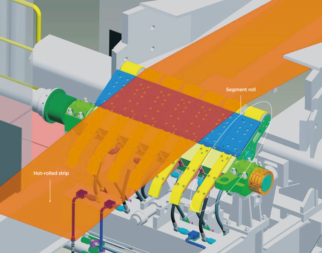
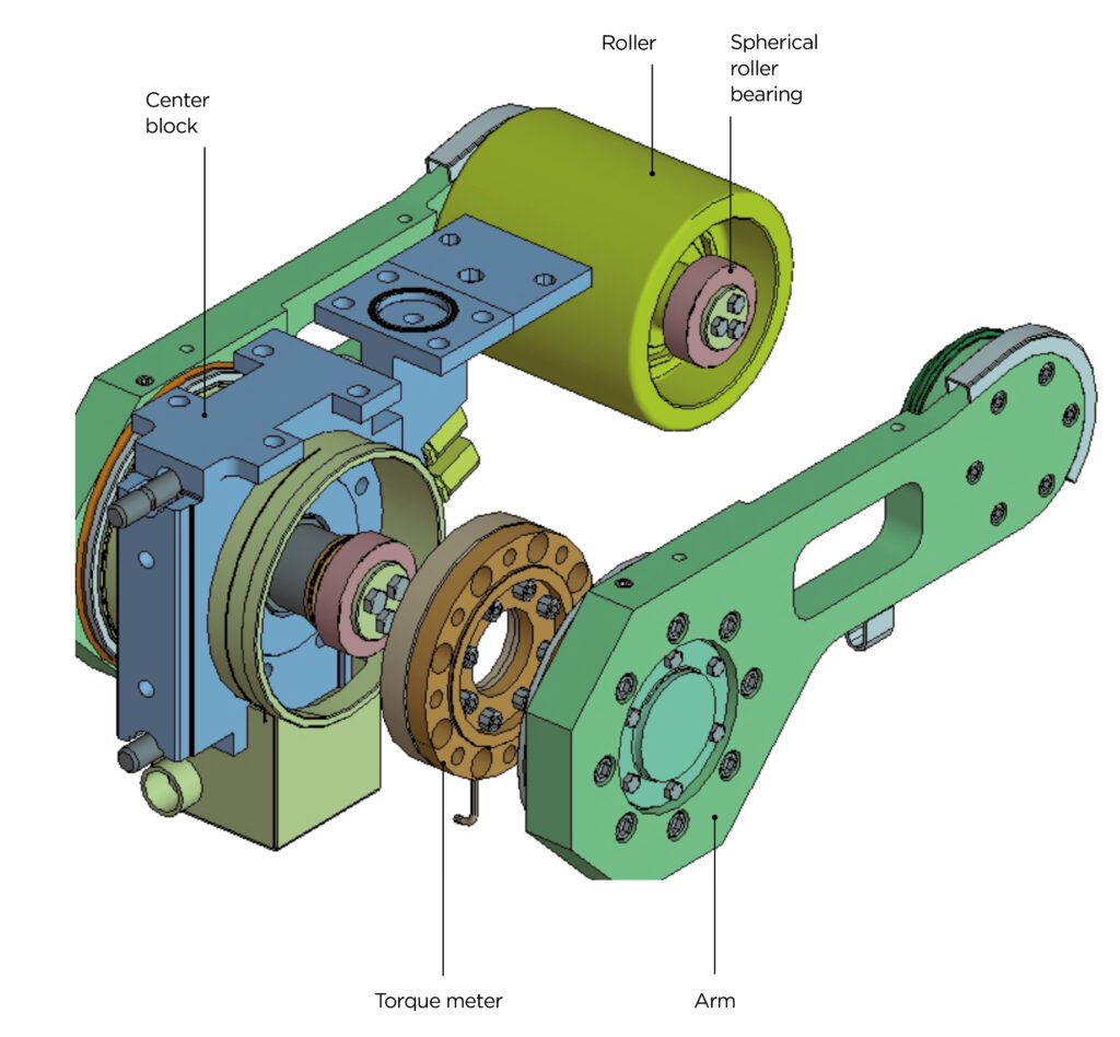
The Looper Shape Meter is a strip-shape-measurement system that is based on the use of torque meters to accurately measure tension distribution across the strip width. It could be shown that torque measurements correspond to a high degree to the actual strip shape. The Looper Shape Meter substitutes the existing looper of the finishing mill. It consists of seven roll segments evenly spaced across the strip width with torque meters installed on both sides of the center block of each segment (Figures 2 and 3). The tensile force measured at each segment is directly received by the torque meters through the arm. The torque that corresponds to the tension distribution in the segment roll is then measured.
The individual torque meters are covered by a shield and air-purged to prevent the intrusion of water and dust. To protect these units against heat radiating from hot-rolled strip, internal water cooling is employed in the center block and in the apron above the center block.
For accurate measurements, it is important to reduce the hysteresis caused by sliding parts. Because the Looper Shape Meter measures tension distribution directly with the torque meter and therefore has few sliding parts, hysteresis-related disturbance is minimized in the measured results. Furthermore, in comparison to the optical devices generally used to measure strip shape, the Looper Shape Meter delivers much more precise information because the sensors acquire a complete picture of the strip shape.
The data from the Looper Shape Meter is sent from the 14 torque meters to the shape-calculating device. At the same time, the looper angle, strip speed, strip thickness, strip width and other data are sent from the Level 1 and Level 2 controllers to the shape arithmetic unit. The calculated strip shape is transmitted to the control pulpit where it is displayed on the operator screen. These results are useful to control stand leveling and roll-bending-force adjustments by the operator, and therefore contribute to stable strip threading-out, prevention of defective strip shape, and tail pinching.
A proven solution
The first Looper Shape Meter has been operating in a hot-strip mill since 2006 where the solution was thoroughly tested. Results show that it has excellent robustness, even under the harsh conditions of hot rolling. For example, in a test to examine temperature, the torque meter remained at around 25°C during approximately ten minutes of continuous rolling – despite a strip temperature close to 900°C. After rolling, there were no signs of water or dust intrusion and the Looper Shape Meter remained in good condition.
As the market demand for hot-rolled strip continues to rise, particularly for high-tensile-strength steels, Looper Shape Meter technology could become a solution for enhanced strip-shape-control accuracy, more stable strip-rolling and threading-out conditions, and therefore productivity improvements.
Reference plant | Type of project
Tata Steel, IJmuiden, the Netherlands | Revamp project
Hyundai Steel, South Korea | Revamp project
Tata Steel, India | India New rolling mill
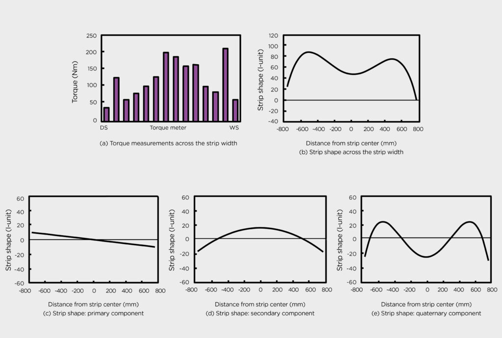
The LSM demonstrated the following measurement results during testing: The final strip thickness was 2.44 mm and the width 1,513 mm. The torque was highest near the strip edges and center, and lower at the quarter point (a). The resulting strip shape calculated shows a smaller elongation on the work side, center buckling and quarter buckling (b). This could be separated into primary, secondary and quaternary components as in (c), (d) and (e), respectively.