A key focus of rolling mill operation is to ensure unparalleled strip quality at the lowest-possible operating costs. A major cost factor in rolling is the energy required for the coolant pumps that supply pressurized water for the cooling of the work rolls. Following extensive laboratory and field tests, an enhanced Power Work-Roll Cooling solution was developed by Primetals Technologies that allows for the required coolant pressure to be markedly lowered. Impressive energy savings of 70 percent can be achieved compared to conventional work-roll cooling systems.
In hot rolling mills, large flow rates of cooling water are required to remove the thermal energy of the roll, which is conducted through the roll surface during strip deformation in the roll bite. Work-roll cooling headers are usually installed at the entry and exit side of the mill stand and permanently apply coolant to the rolls—if necessary, in variable quantities—to limit the roll temperature and the resulting thermal expansion. Up until now, Primetals Technologies has applied a dynamic work-roll cooling system with several cooling headers arranged at the entry and exit side of the mill stand. The cooling headers are equipped with flat-jet nozzles and the system pressure is usually 13 bar.
Improvements in cooling efficiency have recently been achieved by maximizing the area of coolant impingement around the roll circumference on both the entry and the exit side of the mill stand. Nevertheless, the upgraded system still operates at a system pressure of 13 bar and relies on flat-jet nozzles. As the energy consumption of the supply pumps is proportional to the operating pressure, it would be advantageous to operate the cooling system at a reduced pressure to save energy and operating costs. However, according to the experience of Primetals Technologies, this is not possible without reducing the efficiency of the system, especially in the area above the top-side wiper. This is because cooling water accumulates as it has to drain sideways over the wipers, which decreases the cooling efficiency of the lowermost water jets that have to spray through the water before reaching the roll surface (“pool effect”). Increasing the flow rate would not improve this situation either, since the larger pool effect would impair cooling efficiency even more.
To overcome this difficulty, a solution for this problem was derived from the proven Power Cooling technology of Primetals Technologies, which allows for the highest-possible strip-cooling rates at the run-out table. This is achieved by applying pressurized coolant to the top and bottom surfaces of the strip. The situation on the top side of the strip is somewhat comparable to the demands of work-roll cooling, as a huge amount of water drains sideways over the strip edges and a thick water layer accumulates. The efficiency of the Power Cooling system is ensured by utilizing solid-jet nozzles, where the jet speed and impact pressure of the coolant are high enough to penetrate the water and steam layer on the strip surface. The idea now was to adopt the same principle for the cooling of the work rolls, especially on the exit side of the mill stand, where it is most critical.
With the significantly increased water-penetrating capacity of solid-jet nozzles and thus the more concentrated application of coolant on the roll surface, the resultant cooling effect can be maximized.
With the significantly increased water-penetrating capacity of solid-jet nozzles and thus the more concentrated application of coolant on the roll surface, the resultant cooling effect can be maximized. Instead of having to install two or three cooling headers on the inlet and outlet side of a mill stand, only one new cooling header equipped with solid-jet nozzles is required to ensure homogeneous roll-surface cooling. The cooling headers can maintain their fixed position during rolling and are only retracted during a work-roll change. The low-pressure direct-cooling water system, operating at 4 bar, supplies the cooling headers with coolant, which results in energy savings of about 70 percent compared to conventional cooling systems, provided that the flow rates are identical. The Power Work-Roll Cooling system of Primetals Technologies is protected by patent EP3308868B1.
Laboratory Tests
In order to demonstrate the feasibility of the new cooling system, experiments were conducted at a test rig at the Heat Transfer and Fluid Flow Laboratory of
Brno University of Technology in the Czech Republic.
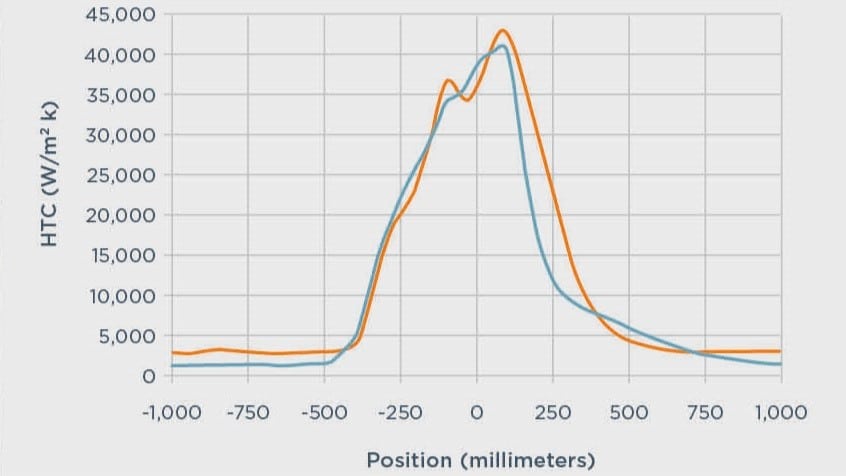
A thermocouple mounted inside an externally cooled rotating roll was utilized to measure the temperature decrease over time, which was then used to perform an inverse calculation of the heat-transfer coefficient. The tests revealed that, when applying the same flow rates, the cooling efficiency of an ensemble of solid-jet nozzles operating at a pressure of 3 bar showed a cooling effect that was at least as good as with flat-jet nozzles operating at 10 bar.
Design Considerations
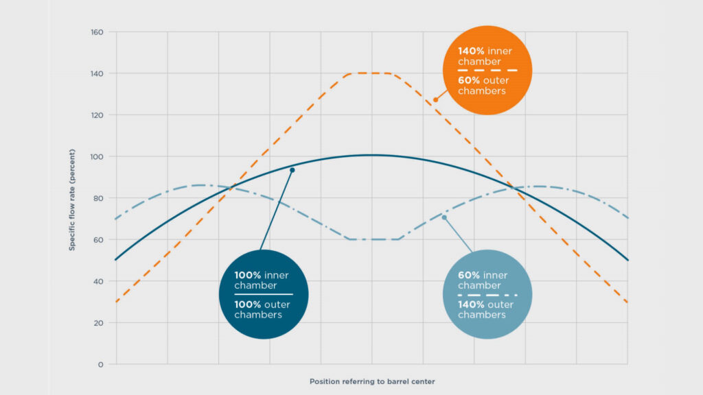
The results of the laboratory tests will be instructive for all future installations of Power Work-Roll Cooling. They will feature a design involving a cooling header that is divided into several discrete, independent spray chambers to enable the specific flow rates to be adjusted in roll-width direction, which is the principle of dynamic work-roll cooling. This can be achieved by separately feeding the center chamber and the two outer chambers with coolant. The flow to these chambers is controlled by flow-control valves. By increasing or decreasing the individual flow rates, the resulting overall flow pattern can be adjusted over a large range without the risk of cavitation at the valves due to the lower operating pressure (Figure 1). This is an essential factor for controlling the thermal expansion of the rolls, which fundamentally influences the profile and flatness of the strip.
Field Tests
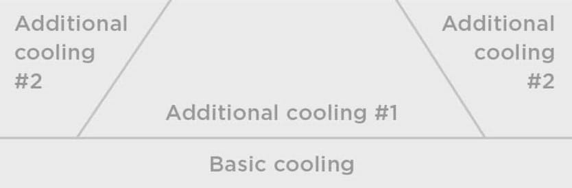
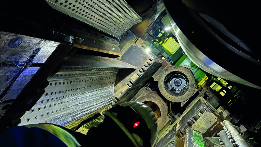
Once this cooling concept was finalized and following the successful completion of laboratory trials, field tests were conducted at the new Arvedi ESP line No. 2 of Hebei Taihang Iron & Steel Group in China. As this mill is equipped with a conventional dynamic work-roll cooling system, the existing cooling-header design needed to be adapted to be compatible with the standard solution from Primetals Technologies. The conventional system features three cooling headers per work roll on the exit side of the mill stand (basic cooling zone, additional cooling zone #1, additional cooling zones #2). These are fed by three individual supply lines. In order to ensure full compatibility and to enable interchangeability of the header types, a customized cooling-header design was developed by Primetals Technologies, as depicted below.
All chambers of the spray header were equipped with the same type of solid-jet nozzles. The basic cooling zone, which is fed from the same line as the conventional entry-side cooling header, features several rows of nozzles with a parabolic spray pattern. This is accomplished by means of a gradually reduced nozzle pitch toward the center of the header. The supply lines for the two additional cooling zones provide water for the three remaining chambers that are located further away from the roll bite.
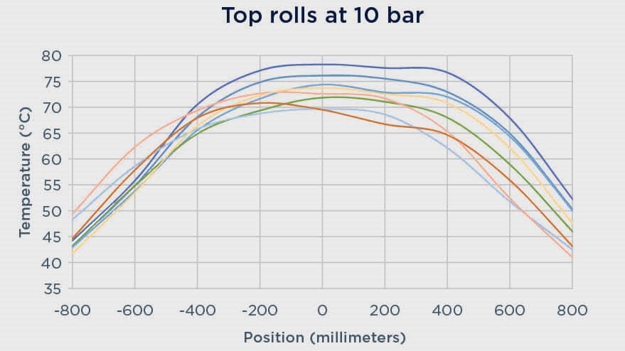
Two sets of exit-side Power Work-Roll Cooling headers were installed and tested in the Arvedi ESP line—namely one high-pressure variant (approximately 10 bar at the spray nozzles) and one low-pressure variant (approximately 3 bar at the spray nozzles). An identical nominal flow rate of both header versions was achieved by increasing the number of spray nozzles for the low-pressure header in accordance with Bernoulli’s equation.
Results show below that the average work-roll temperature is roughly the same for both the low-pressure and high-pressure cooling variants. Thus, with a larger number of spray nozzles and a denser spray pattern, the low-pressure cooling variant successfully compensates for its reduced operating pressure.

Hi-Cr iron work rolls were used during the duration of the tests. Strip with a minimum thickness of 0.8 millimeters was produced. Roll surface quality was excellent for both the low-pressure and high-pressure cooling variants.
Comparison of Arvedi ESP Lines #1 and #2
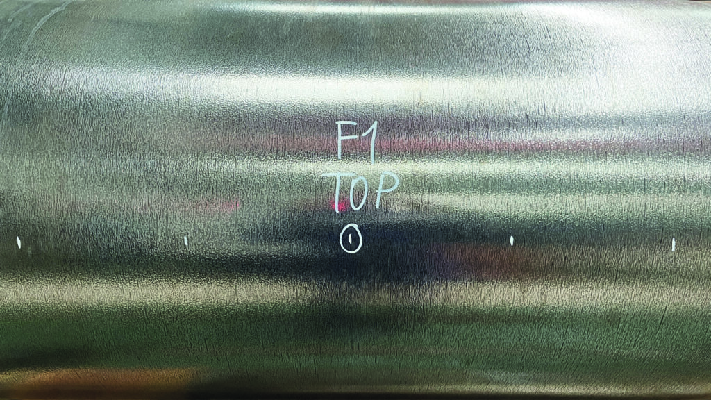
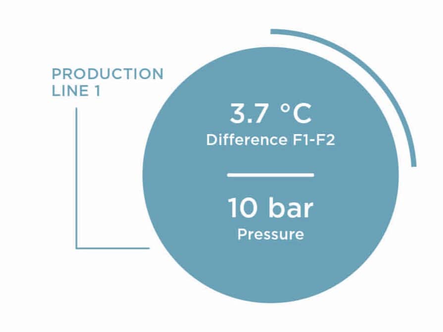
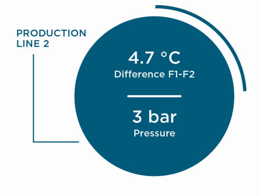
The new Power Work-Roll Cooling system was installed at the Arvedi ESP line No. 2 in mill stand F1 while line No. 1 kept relying on the cooling system that the line was originally fitted with. The width of the strip was larger in line No. 2, and therefore the surface for heat transfer was greater. Because of these factors, a direct comparison of the F1 work rolls of Arvedi ESP lines No. 1 and No. 2 was not possible. To enable a comparison, the F2 work rolls of both lines, which were equipped with the same cooling system, were also included in the overall investigation. The temperatures from multiple measurements taken across the barrel length of the top rolls were used to calculate an average value for the work rolls of stand F1 and F2 (both Hi-Cr rolls), and the difference between both lines was then determined. As shown below, the temperature difference between the F1 and F2 work rolls in lines No. 1 and 2 amounted to only one degree Celsius. It can therefore be concluded that there is no significant temperature deviation between both lines and that both systems basically feature the same cooling performance.
Summary
A new power work-roll cooling system based on the proven Power Cooling technology of Primetals Technologies was developed and successfully tested. As demonstrated by the operating results from the first installation of the new system, the cooling efficiency of the low-pressure and the high-pressure variants are comparable. On the basis of the promising results, it is now planned to establish the low-pressure dynamic cooling solution as the standard work-roll cooling system for all future Arvedi ESP lines as well as for conventional hot-strip mills. The overall energy consumption of the coolant-supply pumps is forecast to be reduced by about 70 percent.